This is an old revision of the document!
Table of Contents
Lapidary machine: more proper name referring to use on rocks. Tend to be less precise or more like faceting machines
Cabbing/faceting machine; instead of arm support has a post with a precise angle adjustment and holder. This might make a good DIY conversion route
Setup types
There are various ways to mount samples based on what you need to do and how much you are willing to spend.
Parallel polishing
This site focuses on IC analysis. Therefore the site focuses on this type
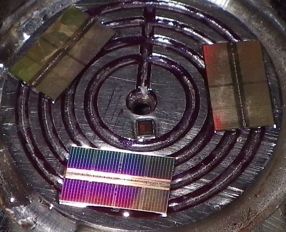
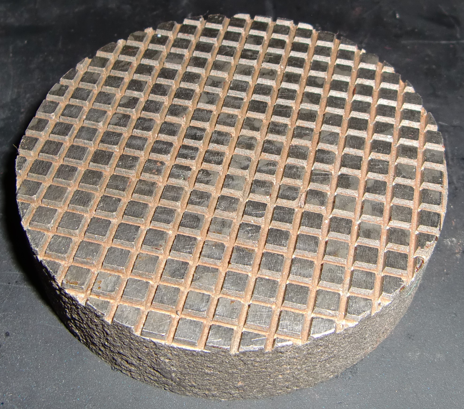
This type of fixture can be identifed by a surface to affix a sample to. Typically this is a stainless surface with indentation marks on it to help wax/glue grip better.
Above: fixture close-up showing wax grooves
Standard
A piston slips up/down. The angle at which the piston contacts the platen is not adjustable.
Three point
Like above but the piston angle is adjustable. This allows more precision and is easier to setup.
Overhead arm
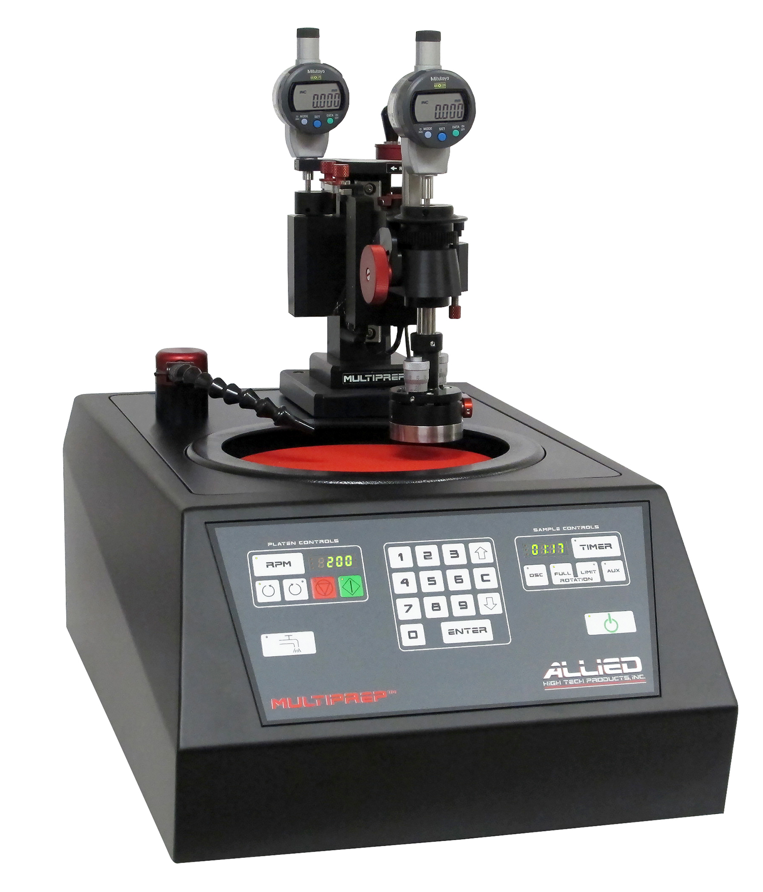
Above: Allied High Tech 15-2000-GI [http://www.alliedhightech.com/Equipment/multiprep-polishing-system-8|Source]
A motorized arm is suspended above the platen.
Example: Allied High Tech 15-2000 MultiPrep System
Advantages
- Less force on platen than side arm design
- Easier to control force?
Disadvantages
- Parts are usually machine/manufacturer specific
- More limited selection
Side arm
The three point polisher is a stand alone object that can be moved from one machine to another. The fixture itself is ground and thus must have tungsten carbide or other hard pads on the bottom to ensure long life. A motorized arm is attached to the machine and turns the fixture via a rubber wheel in contact with the fixture.
Example fixture: Logitech PP6, South Bay Technology 590
Example machine: Logitech LP50, South Bay Technology 920
Advantages
- Machine agnostic: can be used on many different lapping machines
- Higher precision?
- Simpler
- Somewhat scalable: larger size generally yields higher precision
Disadvantages
- Fixture itself is lapped: more powerful machine required and degrades fixture over time
- Tend to be larger than overhead arms
- Larger fixture: larger lapping machine required
- Force can be harder to control: typically adjusted by applying weights
* Pneumatic versions exist
Perpendicular polshing
Designed to polish a thin slice of material at right angle to high precision. Use, for example, to see how IC layers stack up.
Sectioning
Makes a highly polished surface to allow looking at, for example, a weld under a SEM or optical microscope to observe grain boundries. Unlike parallel polishing, these do not have tight control over the angle at which they are polished.
Typically specimins are mounted in epoxy and then bolted into a tear drop shaped fixture.
Wafer
Used for polishing entire wafers, typically for IC manufacturing. These machines tends to be very large
They can typically be identified by having gears and large circular cutouts to hold various size wafers
Cast iron
This isn't a machine so much as a platen that is used manually. Seen entry below
Faceting
Intended for cutting gemstones (ex: diamonds) into shapes for jewelry
Faceting machines share much with lapping machines. However, they trade more movement freedom for lower precision. I'm unclear if a faceting arm can do reasonable parallel polishing
Machine
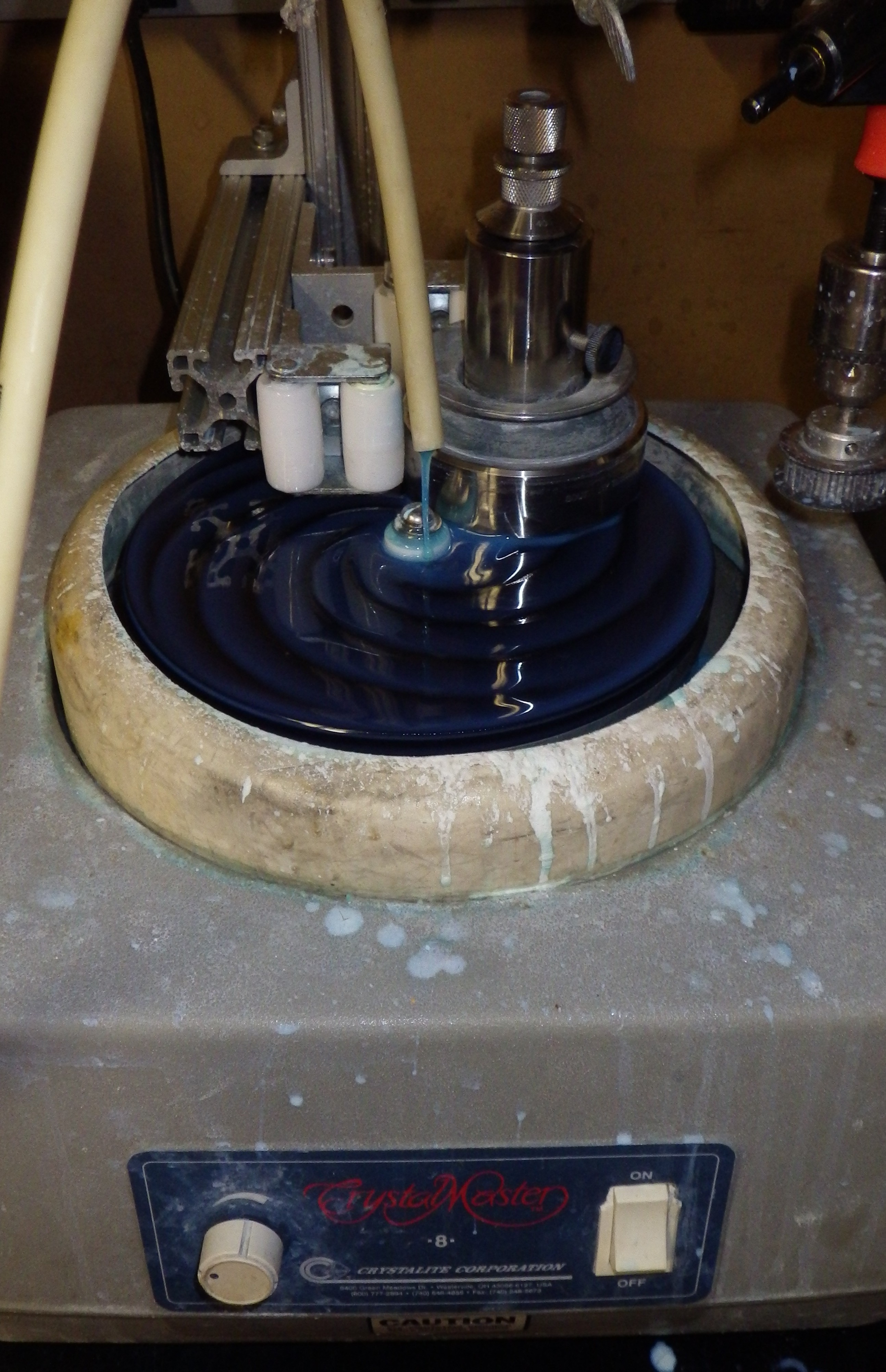
Above: CrystalMaster 8 with South Bay Technology jig. Drive mechanism seen at right although belt is not attached
Samples can be polished manually by moving them in a figure 8 pattern for reasonably even polishing. However, this takes a while and can be tiring. Thus, most all IC work is done on a machine for so called “automatic lapping”.
The main components of a typical lapping machine:
- Lapping plate or “platen”: a ridged surface that spins against sample
- Platen drive motor: motor to spin lapping plate
- Speed controller: how fast the platen rotates
- Fixture drive motor: motor to put a controlled spin on lapping fixture
- Slurry pump: recirculates CMP solution after coming off of the platen
- Support arm: turns fixture and keeps in place
- Slurry reservoir: holds bulk of slurry solution
- Slurry filter: filters out contamination so it doesn't scratch the sample
- Splash guard: as disk spins silica spins out and would make a huge mess if not recaptured
Platen
Beyond IC RE, platen can be made of a variety of materials including:
- Cast iron
- Diamond
- Poromeric pad
However, cast iron and diamond are too abrasive for IC RE and so only polymeric pads are typically used.
Some machines can take magnetic apds such that one can switch, say, between a diamond and cast iron pad. As you should really only be using polymeric pads this feature will probably be less useful.
Above: typical stackup seen on JM machine consisting of (top to bottom):
- MTI 8“ Poromeric Polishing Pad (PSA) for final polishing - EQ-PP-8PSA-PC
- Two 8” Mater Plate ( Backing Plate ) for PSA Diamond plate, Sand Paper & Polishing Pad - EQ-MBP-8-2
- CrystalMaster 8 master lap
The first, the poromeric pad is the most important. It is essentially a soft pad to move abrasive around without actually scratching the die. The next forms a smooth surface on which the poromeric pad rests. Finally, the master lap is the interface to the machine itself and has ridges to keep backing plate in plate.
Originally the machine had a steel backed diamond pad directly on the master lap (attached with adhesive, removed with acetone + heatgun). In this setup the steel backing is much stiffer than the polishing pad and so serves as the backing plate.
Cast iron
Above: cast iron lapping plate
Cast iron lapping plates are typically used with diamond paste to lap optics and metal surfaces smooth. They don't seem to be appropriate for use on ICs. I tried using CMP solution on a cast iron lapping plate and it noticeably corroded it within 10 minutes.
Support arm
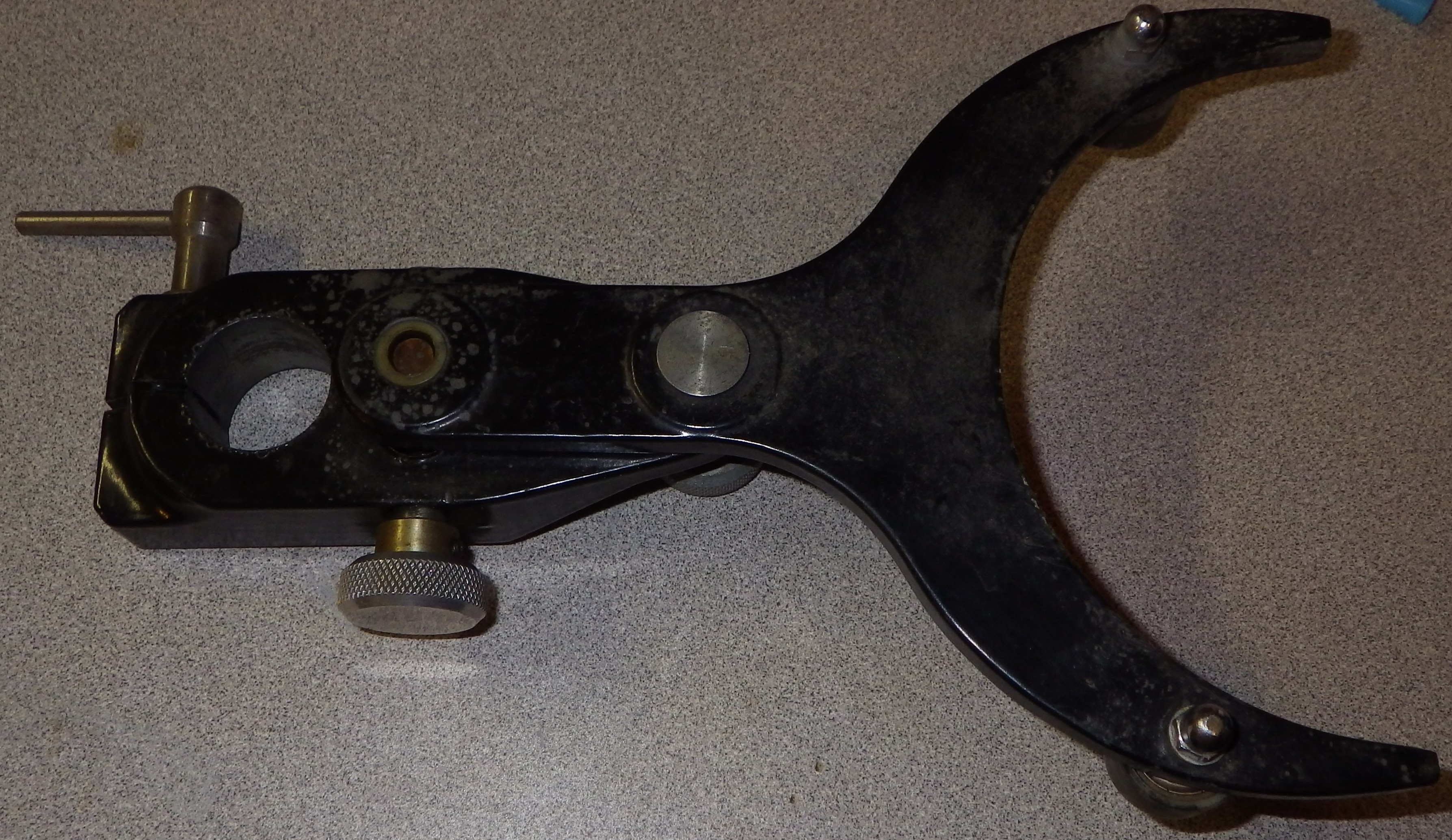
Above: from Logitech lapping machine. Note the screw on the side to make fine angle adjustments
aka:
- Logitech: ?
- MTI: york support
- South Bay Technology: yoke assembly
Most machines have a stiff support arm with two rollers on it. This allows the fixture to rotate along with the machine to evenly lap the sample (planetary motion). They are usually attached to a sturdy post built into the machine
Alternatively, some machines (ex: Allied Tech's) attach the sample to a motor drive mechansim that directly supports the sample
Lost cost alternative: attach some rollers to a steady post and align to lapping machine
Some machines incorporate a fixture drive mechanism into the support arm
Nozzle
Typically uses ridged flexible nozzles like used on CNC machine coolant systems.
JM setup: open tube drips down. I originally used a nozzle but it was harder to clean (was drying out/clogging) and wasn't sure if it really helped since lapping jig conditions the pad
Slurry pump
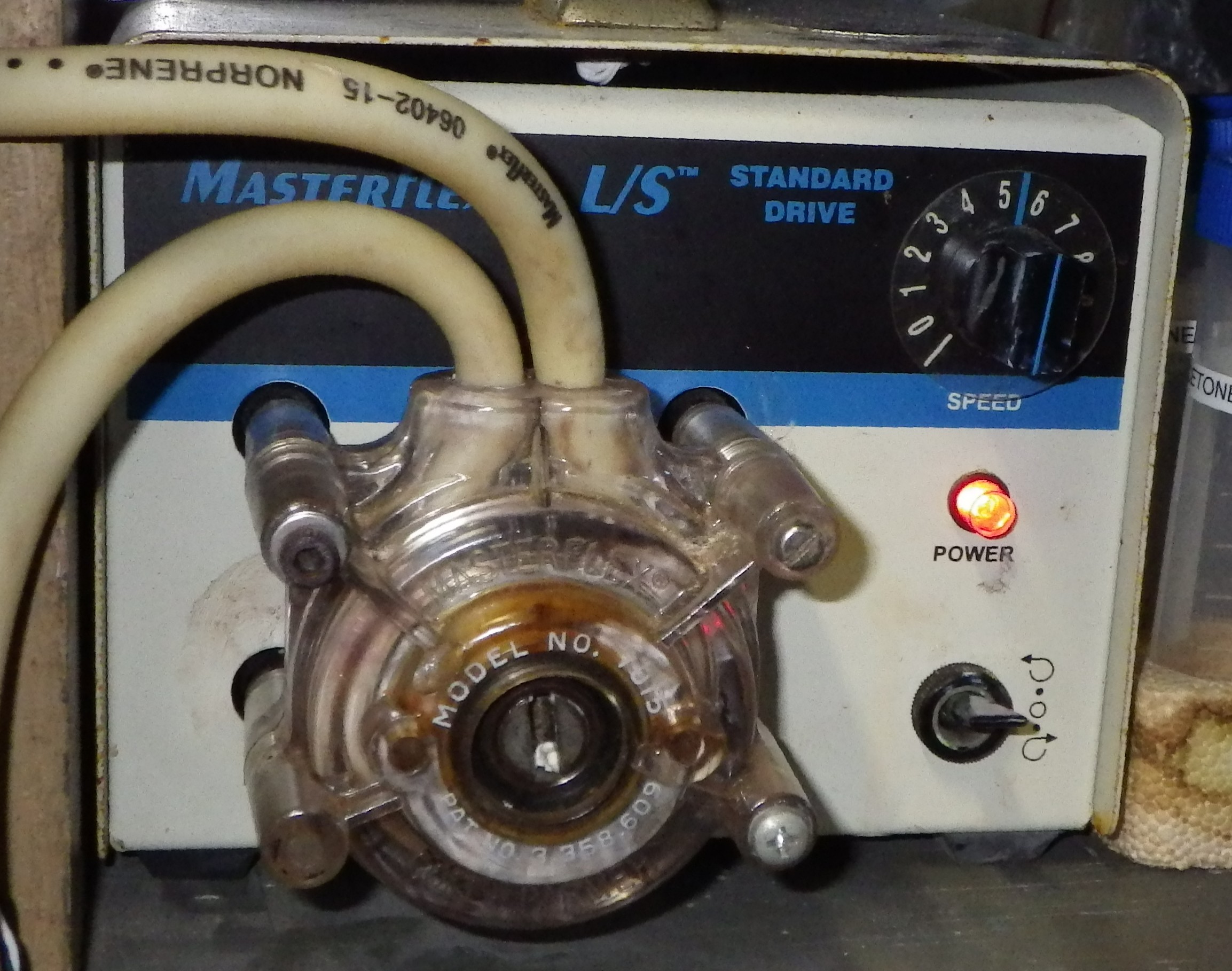
Above: JM setup pump head
Because the abrasive is both corrosive and abrasive, it would be difficult to design a traditional mechanical pump to handle it. Fortunately, the flow rate is small which lends it well to peristaltic pumps.
JM setup:
- Cole Parmer Masterflex L/S
- Cole Parmer 7015 drive head (milled down to fit)
- Cole Parmer 06402-15 (MasterFlex Norprene (Neoprene))
Low cost alternative: put a reservoir above the machine and let it drip down (ex: sepreatory funnel w/ stopcock). You'll have to watch things more closely and the flow rate probably won't be as smooth as pressure will vary with fluid height. As proper flow rate is in fact pretty low should work well enough in practice. Even some higher end machines (ex: Allied Tech) ship with sepratory funnels instead of slurry pumps
Sample holding ("fixturing")
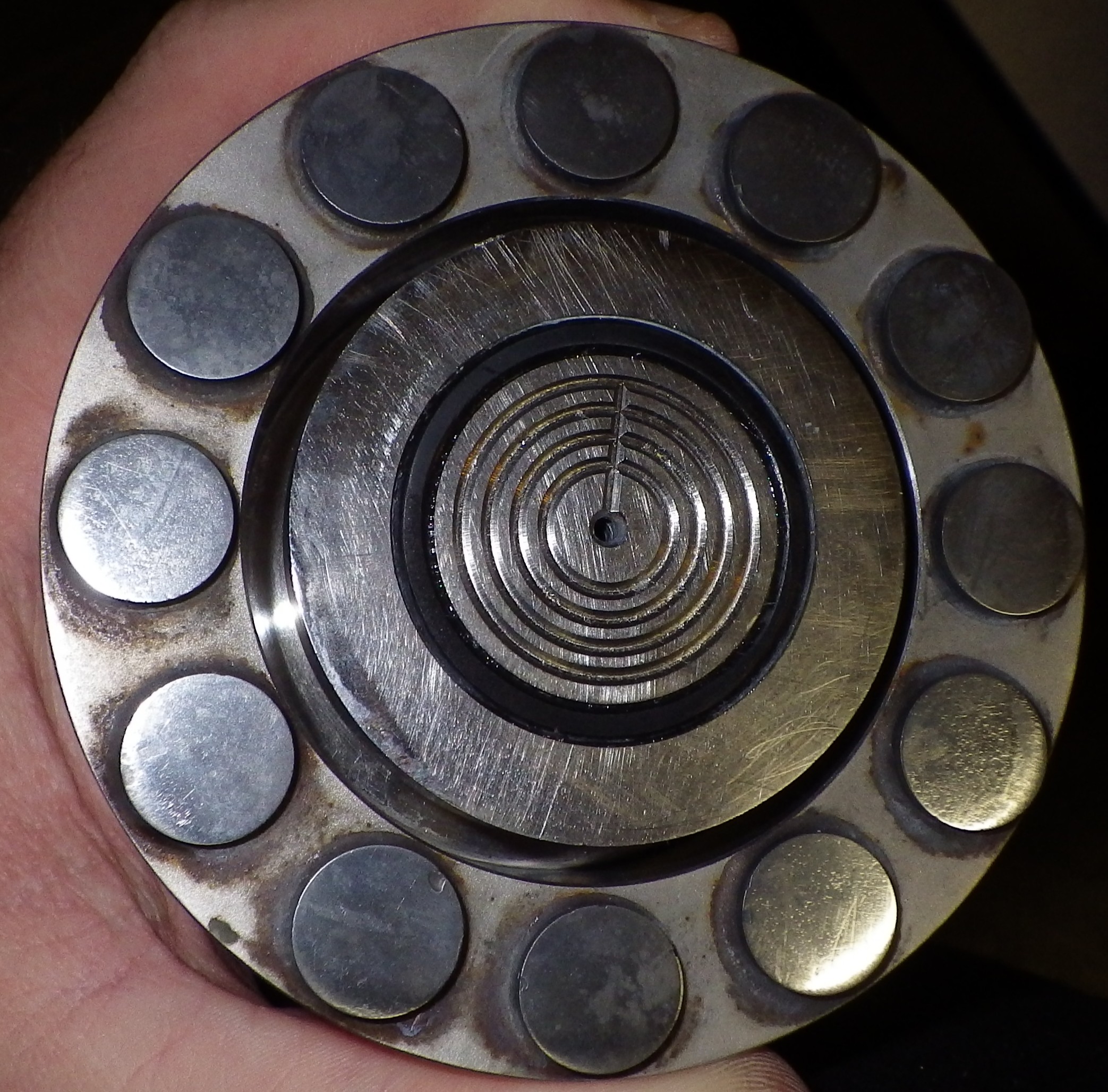
Above: bottom of South Bay Technology jig showing relieved sample holder and carbide pads. Note the center is hollow to allow air to escape for easy sliding
The device used to hold a sample to be lapped is called a lapping jig or lapping fixture. Typically made of stainless steel with carbide pads to resist the corrosive CMP solution. For example, the South Bay Technology 150 uses 303 SS with tungsten carbide pads [ instruction manual ].
Alternatively, the most basic method is to simply hold a die on a finger and press it into a spinning wheel. See tutorial. You won't get as uniform as a polishing but it should suffice if you just care about one particular section
Height control
Most fixtures have a fine pitch threaded on the ram going down the center bore. This allows it to be precision adjusted and locked to a nut to control precisely how much material to be taken off
Most fixtures also have one or two micrometers for monitoring sample height
Tripod
These are like above but include three precision setscrews for adjusting the angle of the center slide relative to the polishing plane. This helps to correct small mounting imperfections. These fixtures are much more expensive.
Example fixture: Logitech PP6
Pneumatic
Most fixtures rely on adding weights to vary the pressure. However, higher end fixtures instead accept air feeds that can be used to more accurately regulate the force applied.
Example fixture: MTI EQ-PF-4-1V
Conditioning ring
A ceramic ring around the sample holder evens out the slurry and filters out some impurities to the sample holder inside. The MTI low cost jig uses a stainless ring instead, I don't know if there is an advantage to one over the other.
The South Bay Technology jig above has a small rubber ring that might have been intended to be some sort of conditioner but unclear how. In any case the carbide pads seem to provide some conditioning
Encased
TLDR: these fixtures are generally intended for sectioning and are not precise enough for parallel polishing
Some machines are designed for samples encased in blocks intended for metallurgy. These are also useful for irregularly shaped samples but these are rarely encountered in IC RE. There are two methods usually employed to encase specimins:
- Epoxy fill (most common)
- Compression mounted.
Example fixture: MTI EQ-PF-3H1W2
Epoxy mounting
TLDR: not suitable for parallel polishing
The epoxy mounting method is nice because is very safe to specimens. Epoxy isn't super cheap but is inexpensive compared to the net cost of doing this type of analysis. The sample is simply put into a well (typically made of silicone I think) that matches the machine size and epoxy is cast into a block. Different epoxies are used depending on requirements (ex: 1 hour cure for quicker processing vs 24 hour cure for higher quality cast).
I've had problems with samples floating up from epoxy getting under them. Most be a hard surface and its probably a good idea to press the die down during casting. A more viscous epoxy might work well at the cost of creating bubbles. Overall, the contamination and uncertainty this introduces doesn't seem to be the best approach.
Compression mounting
Compression mounting is quick and inexpenTLDR: not suitable for parallel polishing
sive per sample. It is intended for sectioning where the particular angle sectioned isn't important. Therefore, its not suitable for parallel polshing. Additionally, it uses high force and the the mix may need to be hot which can risk damaging specimens. See for example MTI's compression mounting powder (EQ-HM-Powder5L) + sample press EQ-MP-300.

